
Views: 20021 Author: Site Editor Publish Time: 2025-01-21 Origin: Site
Introduction
As the global push for carbon neutrality accelerates, hydrogen energy has emerged as a pivotal clean energy carrier. Hydrogen fuel cell vehicles are widely regarded as a key solution to decarbonize the transportation sector. The development of supporting infrastructure, particularly 70 MPa hydrogen refueling stations, is crucial for commercialization. At the heart of these stations lies the high-pressure hydrogen compressor—the most critical, technologically complex, and cost-intensive moving equipment, accounting for up to 45% of a station's total cost. Among compressor technologies, the diaphragm compressor stands out for hydrogen applications due to its zero leakage, oil-free compression, and high reliability.
This article details the comprehensive design, analysis, and successful testing of a 90 MPa high-pressure hydrogen diaphragm compressor, developed to meet the demanding requirements of next-generation hydrogen refueling infrastructure.
1. Technical Specifications & Design Objectives
The primary design goal was to develop a compressor capable of delivering hydrogen at 90 MPa, suitable for 70 MPa refueling stations. Key performance parameters are summarized below:
Parameter | Design Target | Tested Value |
Inlet Pressure | 5 - 20 MPa | 12.53 MPa |
Outlet Pressure | ≥ 87.5 MPa | 87.63 MPa |
Flow Rate (at 12.5 MPa) | ≥ 200 m³/h | 359.0 m³/h |
Outlet Temperature | ≤ 40 °C | 22 °C |
Specific Energy Consumption | ≤ 3.0 kWh/kg | 2.05 kWh/kg |
2. Core Design & Engineering Analysis
The development followed a rigorous engineering process:
Thermodynamic Design: A two-stage compression scheme was adopted with a compression ratio of approximately 2.64 per stage. Calculations confirmed discharge temperatures remained safely within limits.
Diaphragm & Membrane Head Optimization: The core of a diaphragm compressor is its metal membrane. Using a single-exponent generatrix profile, the membrane head was optimized to maximize cavity volume while ensuring the radial stress on the diaphragm remained well below the material's yield strength throughout its cycle. Finite Element Analysis (FEA) validated the design safety.
Dynamic & Structural Analysis: Kinematic analysis ensured the combined piston forces for both stages (61.6 kN and 67.6 kN) were within the 80 kN limit of the baseframe. FEA on critical components (crankshaft, connecting rod, plunger) showed maximum stress levels were 46.7 MPa, 73.8 MPa, and 100.6 MPa respectively, corresponding to high safety factors and confirming structural integrity.
3.Mechanical Integration & Prototype Testing
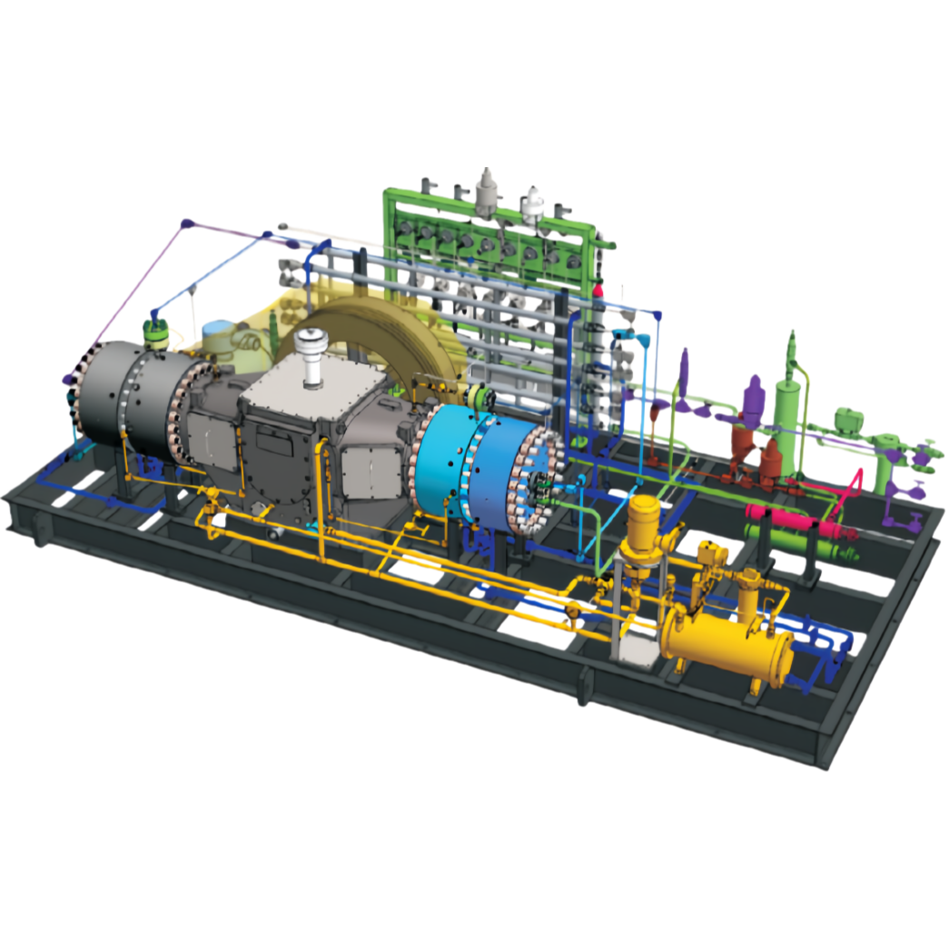
The compressor was engineered as a symmetrically balanced, skid-mounted unit. This configuration offers superior dynamic balance, reduces vibration and bearing wear, and facilitates installation and transportation.
The prototype underwent extensive performance testing on a dedicated platform. Key results, as shown in the table above, not only met but significantly exceeded all major design targets:
Flow rate was 79.5% higher than required.
Energy consumption was 31.7% lower than the target.
Discharge temperature was maintained at a low 22°C.
4. Conclusion
This project successfully demonstrates the complete development cycle—from theoretical design and simulation to prototype manufacturing and validation—of a high-performance, high-pressure hydrogen diaphragm compressor.
The final unit's performance, particularly its high flow rate and exceptional energy efficiency, proves the design's rationality and provides a reliable technical foundation for the advancement of 90 MPa+ hydrogen compression technology. It represents a significant step towards enabling the widespread adoption of high-pressure hydrogen refueling stations worldwide.


